Displaced Intra-Articular Calcaneal Fracture Osteosynthesis: The Sustentaculum Tali Screw Revisited
by Misselyn Dominique1*, Schepers Tim2
1Department of Trauma Surgery, Gasthuisberg University Hospital, Herestraat 49, 3000 Leuven, Belgium
2Amsterdam UMC location AMC Trauma Unit, Amsterdam North Holland, The Netherlands
*Corresponding author: Misselyn Dominique, Department of Trauma Surgery, Gasthuisberg University Hospital, Herestraat 49, 3000 Leuven, Belgium
Received Date: 09 July 2025
Accepted Date: 14 July 2025
Published Date: 16 July 2025
Citation: Misselyn D, Schepers T (2025) Displaced Intra-Articular Calcaneal Fracture Osteosynthesis: The Sustentaculum Tali Screw Revisited J Surg 10: 11381 https://doi.org/10.29011/2575-9760.011381
Abstract
Introduction: Displaced intra-articular calcaneal fracture is considered to be one of the most severe injuries that can be sustained by humans. The optimal treatment approach entails open reduction and plate and screw fixation. Subsequent to the reduction of the fracture fragments, it is recommended that they be affixed to the sustentaculum tali. The placement of a sustentaculum screw with the starting point underneath the posterior talocalcaneal facet, is currently considered an important part of the open reduction and internal fixation of displaced calcaneal fractures. This screw placement is however technically difficult and has a high risk op malpositioning. An alternative approach is presented.The goal of this study was to compare the stability of two different fixation methods of the sustentaculum tali in the osteosynthesis of calcaneus fracture: the “classical” one, recommended in the literature, and an “alternative” one, starting anteriorly and inferiorly to the PTC and following the central axis of the canalis tarsi.
Method: Fourteen identical Synbone®-calcaneal bone models were used. A Sanders II b fracture was induced in every Synbone® model. The calcaneal bones were further divided into two groups (2x7). In one group the “classic” sustentaculum screw was inserted, in the “alternative” group the screw starting anteriorly and inferiorly to the PTC and following the central axis of the canalis tarsi . Before mechanical testing, samples were embedded in a holder using a two-component resin (Kulzer Technovit® 3040). Statistical analysis was conducted using the Statistical Package for the Social Sciences (SPSS) 27, with an independent t-test and analysis of variance (ANOVA).
Results: The alternative method showed less displacement regarding the PTC (p=0.03). Sustentaculum tali fixation did not differ between the two groups(p=0.17).
Conclusion: Under the described testing conditions, we observed superior stability of the alternative stabilization technique for PTC fixation. Regarding the ST fixation both techniques showed similar stability. The results indicate that fixing the ST with a screw starting anteriorly and inferiorly and following the direction of the canalis tarsi might result in improved stability. This means of stabilization is a suitable alternative to the classically recommended screw osteosynthesis of the ST, with less risk of damaging the PTC and having screw in the PSJ.
Keywords: DIACF: Displaced Intra-Articular Calcaneus Fractures; PSJ: Posterior Subtalar Joint; PTC: Posterior TaloCalcaneal Facet; ST: Sustentaculum Tali
Introduction
The calcaneus is an odd-shaped bone, with a low incidence of fracture (less than 2% of all fractures). However, improper reduction and insufficient fixation may lead to a deformation of the hindfoot and subsequent painful post-traumatic arthritis impairing gait and walking. The treatment of Displaced IntraArticular Calcaneal Fracture (DIACF) is based on open reduction and internal fixation to allow early mobilization. During this surgical procedure, it is important to fix the Sustentaculum Tali (ST) because it provides substantial support to the talus [1-5]. The ST , as part of the superomedial fragment, is rarely displaced significantly and is often called the “constant fragment”[6]. It may serve as an end destination for screws drilled under the Posterior Talo-Calcaneal (PTC) facet. An absence of fixation of the ST may cause a decrease of the Böhler’s angle, or in other words, a secondary loss of reduction. [7] Because of the complex anatomy of the calcaneal bone and the narrow structure of the ST, improper placement of these screws is not uncommon, with up to 25% of patients with screws in the PTC or, more commonly, no fixation of the ST. [8,7] A screw in the PTC may severely injure its cartilage with painful post-traumatic arthritis as a result. In addition, radiographic confirmation of correct ST-screw placement has shown to be a challenge [9]. To overcome this risk, several authors have proposed a number of solutions: identifying an ideal starting point and direction based on anatomical studies, the use of a screw targeting clamp, or the determining the effect of different positioning of screws in the ST [2,7,10,11]. In a recent study, the authors examined the impact of different screw positioning under the PTC and found no difference in stiffness [12]. Drilling a screw in the ST parallel to the sinus tarsi axis may be safer to avoid entering the Posterior Subtalar Joint (PSJ). A surgical instrument may be inserted into the canalis tarsi. Doing so will facilitate the identification of the optimal direction drilling direction for the sustentaculum tali screw (Figure 1).
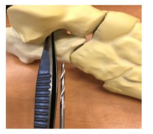
Figure 1: Identifying the sustentaculum with a small instrument (forceps), to guide the drill from the anterior process to the sustentaculum tali
The goal of this study was to compare the stability-the degree of load-dependent displacement of fracture surfaces-of two different fixation methods for the treatment of calcaneus fractures. The first is the “classical” fixation method recommended in the literature, with a screw of the sustentaculum tali drilled under the PTC and the second is an “alternative” fixation method with a screw starting anteriorly and inferiorly of the PTC and following the central axis of the canalis tarsi.
Materials and Methods
Sample Preparation
In fourteen identical Synbone®-calcaneal bone models, a Sanders II b fracture was induced by sawing off the PTC close to the Sustentaculum Tali (ST) using a negative mold-cutting jig to hold the calcaneus and produce identical cuts. This fracture model was chosen because of its frequency [11]. It was also used in other studies [3,13]. The calcaneal bones were then divided into two groups (2×7), depending on the fixation method: classical or alternative. Both methods used the same titanium plates Synthes and 3.5 mm screws, but different configurations regarding the sustentaculum tali screw fixation. [1,2,5,12,14,18] In the classical group, fixation of the ST was achieved with a 3.5 mm lateromedial screw with a 2.5 mm drill underneath the PTC and finishing its course in the ST (Figure 2, classical). In the other group, ST fixation was achieved with a 3.5 mm screw with a 2.7 mm drill from the anteroinferior part of the calcaneus, following the direction of the canalis tarsi (Figure 1) and ending its course under the medial subtalar joint facet (Figure 2, red arrow). In the last group, the screw under the PTC was drilled into the ST. The other screws were positioned in the same way.
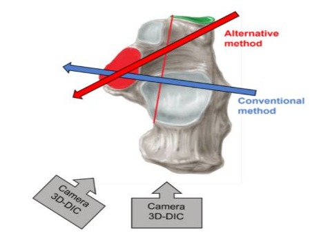
Figure 2: In the classical/conventional group, ST fixation was achieved by drilling the highest screw of the plate under the PTC. In the alternative group, ST fixation was achieved by drilling the plate’s lowest and most anterior screw in a direction parallel to the canalis tarsi.
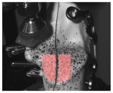
The samples were then embedded in a holder using a twocomponent resin (Kulzer Technovit® 3040) and orientated such that the superior concave surface of the ST faces upwards. To ensure correct and consistent positioning of the calcaneus in the holder during the curing of the resin, a custom 360-degree bubblelevel tool was placed on the superior surface of the ST. After curing, a speckle pattern was sprayed on the calcaneus with an airbrush using black ink to measure the deformation of the sample during the mechanical test using digital image correlation.
Biomechanical Measurements
The samples were tested in FIBEr, our Core Facility for Biomechanical Experimentation (KU Leuven, Belgium). Each sample was mounted on a 3330 Electroforce (TA Instruments, New Castle DE, USA). The calcaneus was loaded on the superior concave surface of the ST with a perpendicular compressive force. The load was applied through a custom 3D-printed pressing tool fitted on the concave surface. The loading protocol started with a preload of 5 N applied at a rate of 1 N/s, after which five precycles were applied between 5 and 10 N at 1 Hz. Next, the load was held constant at 5 N for 5 seconds. Finally, the load was increased at a rate of 50 N/s until failure, the force limit, or the displacement limit of the test device was reached. The force-displacement data were captured at a rate of 100 Hz. During the experiment, two Grasshopper 3 cameras (FLIR Systems, Wilsonville OR, USA) were placed in stereovision to track the deformation of the calcaneus at a rate of 20 Hz (schematically shown in Figure 2). Specifically, two regions were imaged on the calcaneus: ST and posterior subtalar articular surface (further referred to as the superior surface).
Data Processing
After the precycles, the images and force and displacement data were used for further processing in Matlab (Mathworks, Portola Valley CA, USA). The displacement of the ST was assumed to equal the displacement of the pressing tool used to apply the load or the displacement of the test device. The displacement of the superior surface of the calcaneus was derived from the camera images using VIC 3D (Correlated Solutions, Imro SC, USA, integrated by isi-sys GmbH, Kassel, Germany). Specifically, two areas on either side of the fracture plane were segmented, and the displacement of each point in the area was tracked in 3D (see Figure 3).
Afterward, these displacements were spatially averaged to obtain a mean 3D displacement per area. The displacement of the superior surface was obtained by subtracting the respective vector displacements on both sides of the fracture plane. This displacement represents the relative movement of the bone fragment in relation to the remainder of the calcaneus. The energy absorbed by the bone-implant construct during loading was calculated as the area under the force-displacement curve up to the lowest value of the two groups. Finally, a group average curve was calculated by averaging the relative displacements per force level.
Statistical Analysis
The energies of the alternative and conventional samples were statistically analyzed using the Statistical Package for the Social Sciences (SPSS) software 28 (SPSS Inc., Chicago, IL, USA). Analysis of Variance (ANOVA) and Student’s t-test were used to detect significant differences between the measured parameters. Statistical significance was assumed with p < 0.05. The normality of the data was assessed with Kolmogorov-Smirnov and Shapiro– Wilk tests, Q-Q plots and a visual assessment of the histogram of the frequencies. Non-normal data was assessed with the nonparametric Mann-Whitney U test. Power analysis was performed using G*Power version 3.1.9.4 software.
Results
The force-displacement curves of the superior surface and ST are shown in (Figure 4).
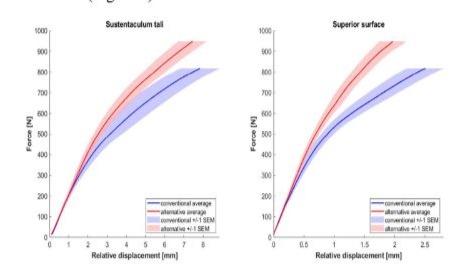
Figure 4: Curves comparing displacement of both fixation methods at STP and PTC (Superior Surface) level.
Each figure shows the group average with the standard error of the mean (SEM). The average load within a group was calculated only up to the test limit of the weakest sample (see Table 1). With the alternative screw placement, there was less displacement for the same loading. For the same displacement, much more force was needed with the alternative screw placing.
T-tests: Data were normally distributed (Shapiro-Wilk and Kolmogorov-Smirnov tests). The alternative screw placing was superior to the classical one: the areas under the curve (load x displacement) were, on average, lower. The difference was not statistically significant (p=0.17, two-tail t-test) for the ST displacement but statistically significant for the superior surface of the PTC (p=0.03, two-tail t-test). Effect sizes (Cohen’s d) were: 0.8 for the ST and 1.4 for the posterior surface. The power (post hoc analysis) was 0.4 and 0.8 for the ST and SS, respectively.
Analysis of Variance (ANOVA)
A one-way ANOVA was conducted to see if there were any statistically significant differences in the means of three or more unrelated groups.. The significance was 0.000, meaning it was smaller than the tabulated value. Our null hypothesis was significant.
Discussion
The goal of this study was to compare the load and displacement of calcaneal model fractures fixed with alternative screw positioning and compare them to the classical screw placement method. Our null hypothesis stated that both methods of screw positioning do not differ in mechanical stability during the experimental fixation of calcaneal fractures. We found a more stable situation for both parts of the fractured calcaneal bone models when using alternative screw positioning. For the loading conditions investigated, there was no significant difference in stability between the alternative fixation and the conventional/classical fixation. The stability of the upper part of the PTC facet was significantly improved compared to the conventional fixation. This might be related to a position more perpendicular to the central axis of this facet: the most cranial screws were fixing the osteotomy fracture, with no need to be drilled in the sustentaculum tali. Repair of the PTC is the primary goal of osteosynthesis of DIACF; this alternative fixation may be advantageous in clinical practice. In addition, drilling a screw in the ST following a path parallel to the sinus tarsi may have less chance of damaging the PTC facet, making the procedure safer and easier to perform. An a priori power analysis was not possible. The post hoc analysis revealed a low power for the ST fixation test of difference (0.4). We used a limited number of synthetic models. However, despite a non-statistically significant difference in ST fixation, we observed high effect sizes (0.8 and 1.4 for the ST and the posterior surface, respectively) and a statistically significant difference in the fixation of the PTC fracture (p=0.03). Moreover, the average load within a group was calculated only up to the failure load of the weakest sample, which was the one with classical fixation. The alternative fixation required a higher average load to achieve displacement, similar to the classical fixation screw placement. We used artificial bones that do not match perfectly the mechanical properties of the real calcaneus. However, these models offer more consistency than cadaveric bone, especially in case of repeatable testing conditions. They were also identical models with identical fracture patterns, allowing a comparison between the two screw positions. Testing on cadaver bones may be the next step because it is considered as the gold standard in spite of the difference of bone conditions: cadaveric specimen are older than patients with calcaneal fractures [8]. Even if more data are needed before recommending this alternative screw fixation, it should be considered in clinical practice, as it presents a more straightforward approach for the fixation of the “constant fragment” of the calcaneal fracture, a task that remains technically challenging osteosynthesis.
References
- Bussewitz B, Hyer Ch (2015) Screw Placement Relative to the Calcaneal Fracture Constant Fragment: An Anatomic Study. J Foot & Ankle Surg 54: 392-394.
- De Boer A, Van Lieshout E, Vellekoop L, Knops S, Kleinrensink GJ, et al. (2017) 2D and 3D assessment of sustentaculum tali screw fixation with or without Screw Targeting Clamp. Injury, Int. J. Care Injured 48: 2864-2871.
- Pang QJ, Yu X, Guo ZH (2014) The sustentaculum tali screw fixation for the treatment of Sanders type II calcaneal fracture: A finite element analysis. Pak J Med Sci 30: 1099-1103.
- Sanders R (1992) Intra-articular fractures of the calcaneus: Present state of the Art. J Orthop Trauma 6: 252-265.
- Zwipp H, Tscherne H, Thermann H, Weber T (1993) Osteosynthesis of Displaced Intra-articular fractures of the calcaneus. Clin Orthop 290: 76-86.
- Stephenson (1983) Displaced fractures of the os calcis involving the subtalar joint: the key role of the superomedial fragment. Foot Ankle 4: 91-101.
- Qiang M, Chen Y, Zhang K, Li H, Dai H (2015) Effect of sustentaculum screw placement on outcomes of intra-articular calcaneal fracture osteosynthesis: A prospective cohort study using 3D CT. International Journal of Surgery 19: 72e77.
- Janzen D, Connell D, Munk P, Buckley R, Meek R, et al. (1992) Intra-articular Fractures of the Calcaneus: Value of CT Findings in Determining prognosis. AJR 158: 1271-1274.
- Gitajn L, Toussaint RJ, Kwon JY (2013) Assessing Accuracy of Sustentaculum Screw Placement During Calcaneal Fixation. Foot Ankle Int 34: 282-286.
- Olexa Th, Ebraheim N, Haman S (2000) The Sustentaculum Tali: Anatomic, Radiographic and Surgical Considerations. Foot Ankle Int 21: 400-403.
- Vosoroughi A (2022) Different types and epidemiological patterns of calcaneal fractures based on reviewing CT images of 957 fractures Foot and Ankle Surgery 28: 88-92.
- Pazour J (2021) Does the position of a sustentacular screw influence the stability of a plate osteosynthesis of a calcaneal fracture? A biomechanical study. Proc IMechE Part H:J Engineering in Medicine1–8 IMechE 235: 993-1000.
- Lin PP, Roe S, Kay M, Abrams CF, Jones A (1998) Placement of screws in the sustentaculum tali: a calcaneal fracture model. Clin Orthop 352: 194-201.
- Albert MJ, Waggoner M, Smith JW (1995) Internal fixation of calcaneus fractures: An anatomical study of structures at risk. J Orthop Trauma 9: 107-112.
- Bailey EJ, Waggoner SM, Albert MJ, Hutton WC (1997) Intraarticular calcaneus fractures: a biomechanical comparison of two fixation methods. J Orthop Trauma 11: 34-37.
- Geerling J (2009) Intraoperative 3D Imaging in Calcaneal Fracture Care-Clinical Implications and Decision Making. J Trauma 66: 768773.
- Phisitkul P, Sullivan JP, Goetz J, Marsh J (2013) Maximizing Safety in Screw Placement for Posterior Facet Fixation in Calcaneus Fractures: A Cadaveric Radio-Anatomical Study. Foot & Ankle International 34: 1279-1285.
- Rammelt S, Zwipp H (2004) Calcaneus fractures: facts, controversies and recent developments. Injury 35: 443-461.
- Zhang L, Wang J, Guo X, Qin B, Yi G, et al. (2018) Three-Dimensional (3D) Computed Tomographic (CT) Assessment of the Sustentaculum Tail to Find Distinctive Characteristics: Implications for Surgery 24: 8417-8421.
© by the Authors & Gavin Publishers. This is an Open Access Journal Article Published Under Attribution-Share Alike CC BY-SA: Creative Commons Attribution-Share Alike 4.0 International License. Read More About Open Access Policy.