A Review of Medical Silicone 3D-Printing Technologies and Clinical Applications
Eric Luis*, Hang Liu, Juha Song, Wai Yee Yeong
Singapore Centre for 3D Printing, School of Mechanical and Aerospace Engineering, Nanyang Technological University, Singapore
*Corresponding author: Eric Luis, Singapore Centre for 3D Printing, School of Mechanical and Aerospace Engineering, Nanyang Technological University, N3.1-B2C-03, 50 Nanyang Avenue Singapore 639798, Singapore. Email: G001@ntu.edu.sg, g38lui2000@yahoo.com
Received Date: 16 July, 2018; Accepted Date: 20 July, 2018; Published Date: 25 July, 2018
Citation: Luis E, Liu H, Juha S, WY Yeong (2018) A Review of Medical Silicone 3d-Printing Technologies and Clinical Applications. J Orthop Ther: JORT-1104. DOI: 10.29011/2575-8241. 001104
1. Abstract
This paper discusses medical grade silicone use in the production of medical implants and devices and reviews the state-of-the-art silicone 3D printing technologies including stereolithography [1], moisture-cured extrusion [2], heat-cured extrusion, hybrid jetting and UV-extrusion [3] and freeform reversible embedding [4] including PICSIMA [5]. The advantages and disadvantages of each method are discussed in detail and the challenges unique to silicone 3D Printing are highlighted.
2. Keywords:Additive Manufacturing; Medical Devices; Medical Implants; Silicone 3D Printing; Silicone Resins;
3. Introduction
Silicone resins are thermoset materials which start out in liquid form and cures irreversibly into solid state with heat. The key attributes of liquid silicone resin (LSR) which make it the ideal material of choice include its hardness, tensile strength, compression strength and fluid resistance. Medical grade silicones, in addition, are selected for their biocompatibility and bio-implantability. The benefits of medical-grade LSR over other elastomeric materials include :1) its Bio-inertness in compliance with ISO 10993, USP Class VI and RoHS standards, 2) its ability to be sterilized by a variety of methods such as Autoclave, ETO, E-beam and Gamma-radiation processes, 3) its stability over a wide range of temperatures 150 F to 450 F and 4) its ability to maintain its resilience, flexibility and capability to transfer mechanical force at extreme temperatures. Using the standard ISO 10993 which evaluates the biosafety of materials in contact with the body, medical grade silicones can be grouped into 3 categories, namely: limited exposure, prolonged exposure and permanent contact. Limited exposure products have less than 24-hour contact with skin, mucosal membranes or breached surface. Prolonged exposure products have surface contact or are implanted more than 24 hours and up to 30 days and require tests protocols for haemolysis, genotoxicity, toxicity and intramuscular implantation with histopathology. Permanent contact silicone products are implanted for more than 30 days and require test protocols for carcinogenicity, chronic toxicity and developmental toxicity.
Silicone was first used for urethral implantation in 1950 and subsequently for shunts and interphalangeal joint silicone replacement prosthesis. It was not until 1962 that silicone breast implant made its debut and its development continued through the 1990s. Unfortunately, the use of silicones for meniscus replacement in knees have not been described in literature. Typical medical application of silicones is shown in (Table 1).
Its use in silicone implants and extracorporeal equipment and devices are discussed below. Conventionally, silicone implants have been manufactured by direct or indirect molding techniques [15]. Since 2015, only a limited number of silicone 3D Printing, also known as additive manufacturing, technologies have been introduced such as stereolithography [1], moisture-cured extrusion [6], hybrid jetting and UV-extrusion [3] and freeform reversible embedding [4]. While these methods are only capable of printing industrial-grade silicones, only heat-cured extrusion technology is capable of printing medical grade silicones.
4. Silicone Implants
In 1946, F. Lahey first reported the use of silicone stents for bile duct repair [6]. Subsequently, silicone has been used to encapsulate and insulate electronic cochlear implants and cardiac pacemakers [7]. Recently, it has also been used for the production of intraocular lens, replacement of vitreous humor and restoration of the continuity of median and ulnar nerves in the forearm [8,9]. In 1962, Cronin. et al, [11] implanted the first pair of silicone gel-filled breast implants. Despite its approval for use by the U.S. Food and Drug Administration since 2006 [10], its long-term safety profile remained a major concern [16,17]. In contrast to Balk et al. which showed equivocal long-term health outcomes of silicone breast implants [18],Singh et al., in a 5 to 8-year follow-up, showed that these implants did not increase the risks of systemic diseases or suicidal rates when compared to saline implants [19]. In 1968, A. Swanson developed the first interphalangeal implants for the hands and feet. These implants were shown to be safe without provoking any immunological or systemic reactions [12,20]. Subsequently in 1973, F. Mazas, et al. developed a total knee silicone prosthesis with shock absorbing capabilities [20]. In reconstructive and plastic surgeries, silicone implants have also been used for nose and chin augmentation.
5. Extracorporeal Equipment and Devices
Medical grade silicones are also used in the production of tubings and membranes of extracorporeal heart-lung bypass machines and blood oxygenators owing to its biocompatible, hemo-compatible and gas permeable properties [13]. In 1968, W. Robb also developed silicone membranes which can be used to extract oxygen from fresh water [14].
6. Silicone Additive Manufacturing Technology
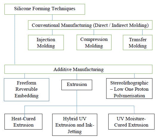
Conventionally, silicone parts or end-products have been manufactured by the molding process or indirect casting. Molding is, however, a major technical barrier since the molding process or mold fabrication is time consuming and expensive when only a few parts are needed. The molding process is also unable to manufacture hollow silicone parts with complex internal architectures or produce parts requiring multi-materials. The recent advent of various silicone AM technologies allow potential space for flexible applications such as components for soft robotics, wearable and custom assistive or rehabilitation devices. The current state-of-the-art technologies in silicone 3D printing are shown in the chart below. This section provides a review on the state-of-the-art AM technology for silicone printing. Current available techniques for silicone 3D printing described in literature are Freeform Reversible Embedding, Stereolithographic-ulltraviolet- (SLA-UV based vat photopolymerization), combined extrusion and ink-jetting, extrusion-based techniques in combination with UV-cured, moisture-cured and heat cured technologies. A comparison of the silicone printing features for available AM techniques is shown in (Table 2) below.
6.1. Freeform Reversible Embedding (FRE) using Carbapol [4]
6.1.1. The Experimental Setup for Freeform Reversible Embedding: Hinton et al. introduced this system in 2016, as shown in (Figure 1)[4].
The FRE Printing Process was performed using MakerBot 3D Printer with a custom designed syringe pump to extrude the PDMS ink Sylgard 184 which has been degassed in a planetary centrifugal mixer. The 3D models for printing were designed using SolidWorks CAD software. All STL files were processed by Slic3r software and sliced into 200 μm thick layers to generate G-code instruction, which was sent to the printer using Pronterface, an open source 3D printer host software suite. Before 3D printing, PDMS ink was drawn into a 10-mL plastic syringe and capped with a 400 μm-ID 0.75’ stainless steel needle tip. This extruder needle nozzle was positioned at the bottom center of the Carbapol support bath. The typical print speed is set at 20mm/s. Post-curing of the PDMS is performed for 72 h at room temperature or for 4 h in an oven at 65°C. The prints were then released from the support by immersing in PBS adopted from [4]).
6.1.2. The Principles of Freeform Reversible Embedding: The working principle of the system leverages on the immiscibility of the hydrophobic PDMS in the hydrophilic Carbopol support. The printing is freeform and is completed layer-by-layer. The Carbapol support fluidizes when the 3D printer needle moves through it and solidifies when PDMS is extruded within it. After printing and curing, the phosphate buffer solution is used to release the embedded PDMS prints.
6.1.3. Proof of Concept of Freeform Reversible Embedding: As a proof-of-concept, Sylgard 184 PDMS is used successfully to 3D print linear and helical filaments via continuous extrusion and cylindrical and helical tubes via layer-and-layer fabrication. These 3D printed tubes are manifold and perfusable, as shown in the (Figure 2) below.
6.1.4. Pros and Cons of the Freeform Reversible Embedding: The advantages of this FRE printing system are that: 1) it can print wide range of biomaterials which are hydrophobic in nature, using a hydrophilic support. Cycloaliphatic epoxies and fluoroelastomers may also be adaptable to FRE printing using Carbopol, 2) the Carbapol supports are highly stable over long periods of time, 3) it has a high degree of accuracy and precision of printouts and 4) it has a low cost of implementation of its open-source hardware and software tools. The disadvantages of this FRE printing system are that 1) it does not work well for lateral fusion, since no lateral pressure can be generated by the support. This is in contrast to the vertical fusion which can be generated by the printouts for the laying down of additional vertical layers to aid fusion of layers below, 2) Carbapol support may be trapped within the voids inside the print, 3) long curing times are necessary, 4) postcuring is required and 5) the low elastic modulus of pre-and post-cured PDMS restricts the 3D geometries that can be printed and 6) it cannot print medical grade silicone
6.2. Hybrid UV-Extrusion and Ink-Jetting Technique [3]
6.2.1. The Experimental Setup of the Hybrid UV-Extrusion and Ink-Jetting system: The hybrid system, as shown in (Figure 3), consists of three piezoelectric-pneumatic material jetting printheads, one solenoid-actuated material extrusion printhead, one pneumatic material extrusion printhead and a UV lamp.
Three controlling units sits on a 3-axis motion stage to actuate the piezoelectric stacks by sending out the voltage signals, and one controller coordinates the air-pressure in the extrusion-based printheads. The Slic3r software creates the toolpaths for the multiple nozzles. The UV-curable silicone used contains the photoinitiator, 2-Hydroxy-2-methyl propiophenone and has a dual UV/moisture curing mechanism. The polymerization process completes within a few seconds after the UV exposure with 365 nm wavelength. The full mechanical properties are achieved after exposure to the environmental moisture for 7 days.
6.2.2. The Principles of the Piezoelectric-pneumatic material jetting AM in the Hybrid system: The conventional material jetting system, formerly known as inkjet printing, is compatible with fluid shaving a maximum viscosity of 40 mPa.s. In these systems, fluids with an Ohnesorge number (
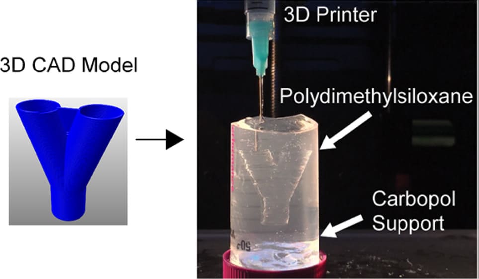
Figure 1: Experimental testbed of FRE using Carbapol (a) 3D Printing of hydrophobic PDMS prepolymer resins within a hydrophilic Carbopol gel support. Carbopol maintains the dimensional stability of the PDMS prepolymer within the support for up to 72 hours. (adopted from [4])
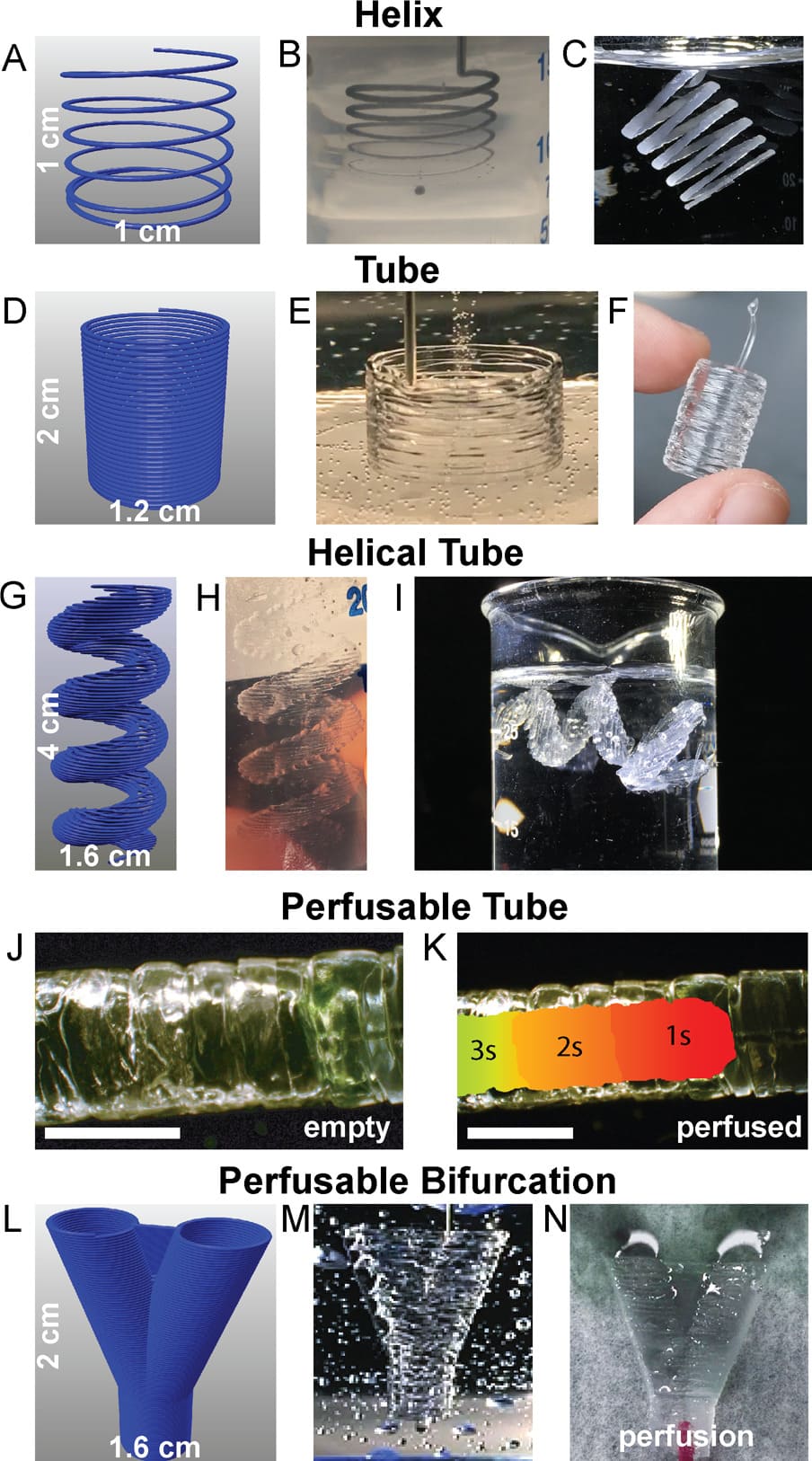
Figure 2: (adopted from [4]) Representative FRE printed PDMS structures using the Carbopol support. (adopted from [3]); (A): The Carbopol gel is capable of supporting freeform extrusion such as this helical path rendered in G-code; (B): The helical extrusion appears identical to the G-code when embedded in the Carbopol (dyed black for visualization); (C): After curing and release, the PDMS helix print retains its geometry when floating in water; (D): G-code for a cylindrical tube (E): The layers of PDMS filaments fuse into a monolithic surface; (F): After curing and release, the printed tube remains fused between layers and is stiff enough to maintain its geometry while being handled; (G): The G-code for more complex helical tube; (H): the helical tubes are supported within the Carbopol; (I): Release of the helical tube from the Carbopol gel shows the maintenance of geometrical features, supported in water because it cannot support its own weight, even when cured; (J): A PDMS tube to demonstrate the manifold nature of the print’s outer surfaces (scale bar is 4 mm); (K): A time-lapse heat map of dye perfused through the tube (scale bar is 4 mm.); (L): G-code of a bifurcation withwebbed fork for stability; (M): The FRE printed PDMS bifurcation embedded in the Carbapol; (N): Perfusion of dye through the bifurcation, splitting fluid flow.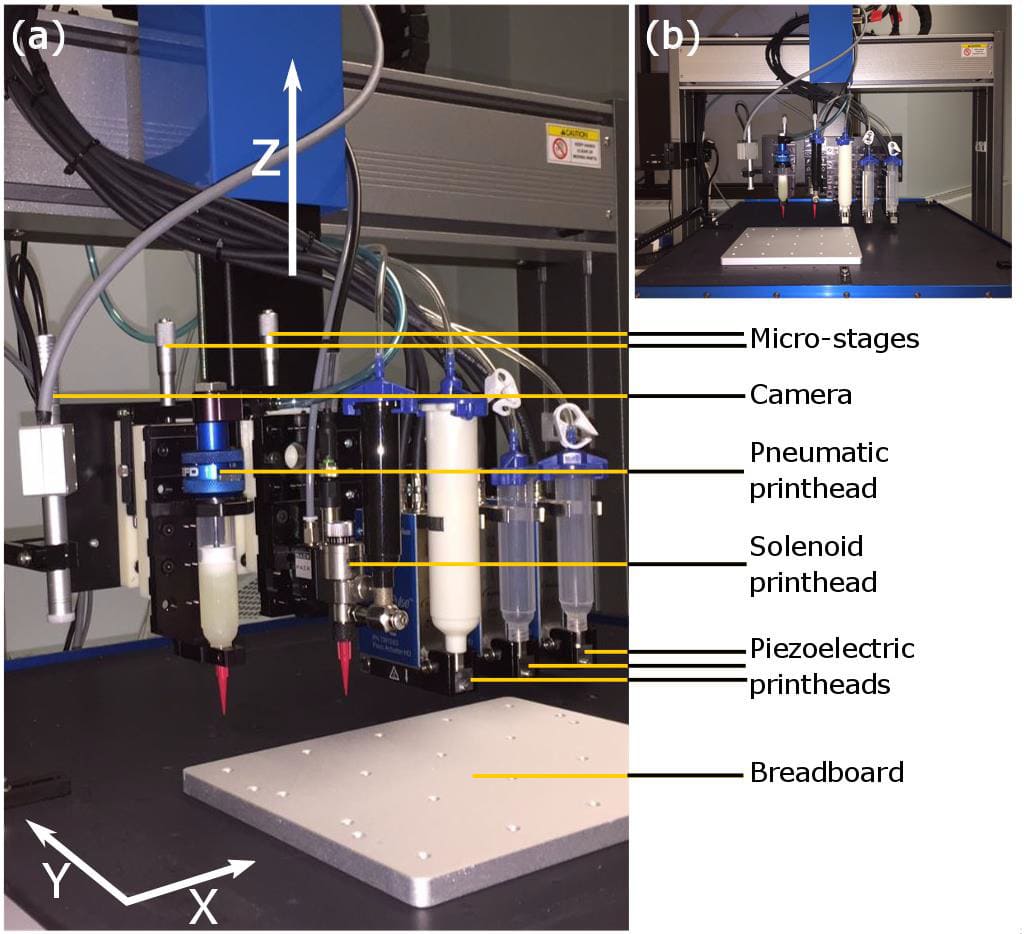
Figure 3: Experimental Setup of the Hybrid UV-Extrusion and Ink-Jetting system: (a) Main components; (b) Front view (adopted from [3])
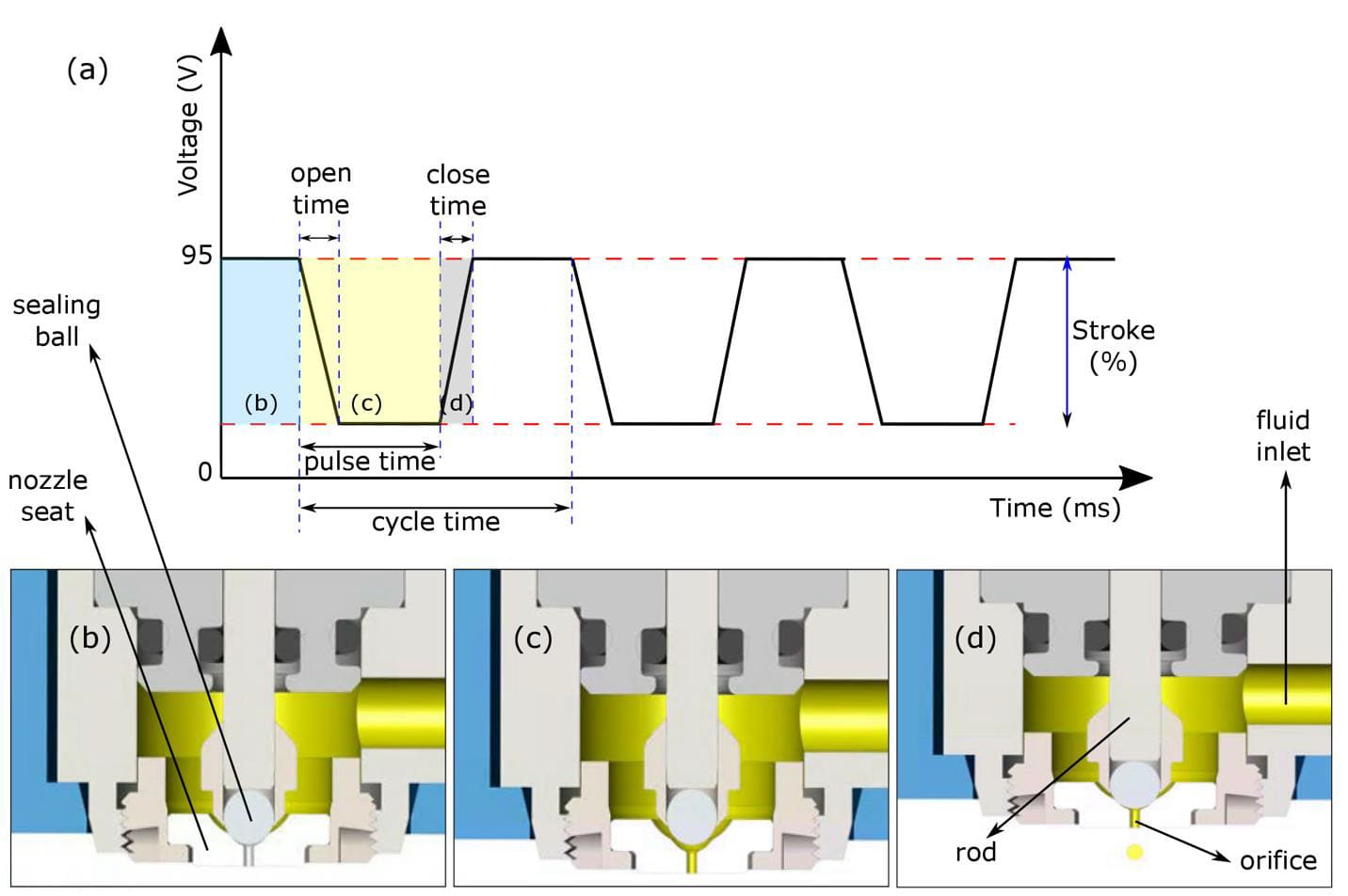
Figure 4: ( adopted from [3]) The working principle of the piezoelectric-based material jetting; (a): The plot shows the voltage signal sent to the piezoelectric stacks for three complete cycles, open time indicates how fast the valve is opened, close time indicates how fast the valve is closed, pulse time is the total time the valve is open, and the cycle time is the total duration of one open/close cycle; (b): Corresponds to the blue region of the plot showing the time duration that the valve is closed; (c): Corresponds to the yellow region of the plot when the orifice is open and filled with the material; (d): Corresponds to the grey region of the plot showing the closing ramp.
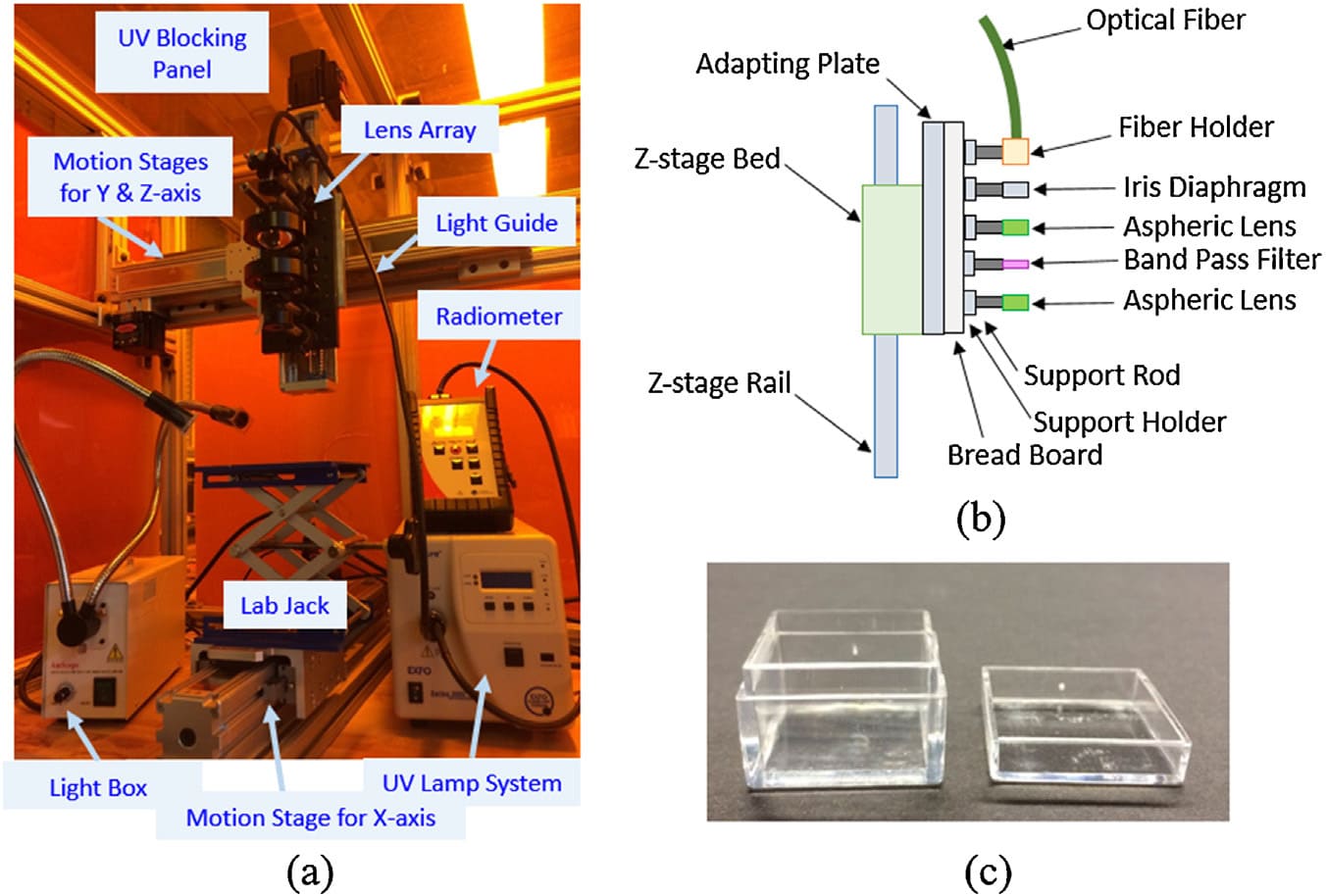
Figure 5: Experimental testbed of combined SLA-LOPP system: (a): The overall setup, (b): Schematic diagram of the lens array, and (c) acrylic boxes as a silicone resin container. (adopted from [1]).
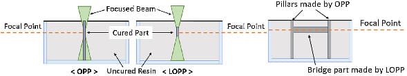
Figure 6: Schematic diagram of one-photon polymerization (OPP) and low one-photon polymerization (LOPP) showing printing of H-shape structure for proof of LOPP concept. (a): Front view; (b): Side view. (Adopted from [1])
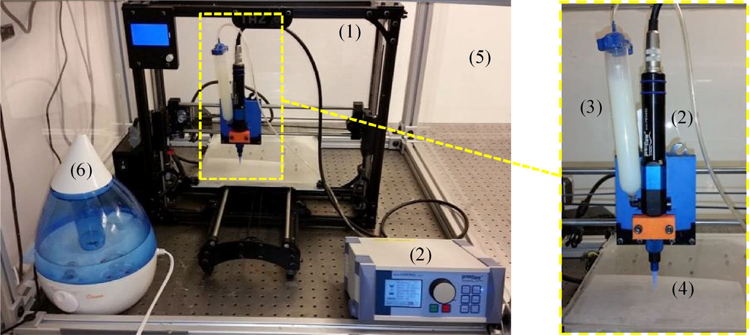
Figure 7: Experimental setup for moisture-cured extrusion-based silicone AM: legends: (1): Motion control platform; (2): Progressive cavity pump and controller; (3): Pressurized syringe barrel; (4): Tapered nozzle; (5): Enclosed build chamber; and (6): Humidifier. (Adopted from [2])
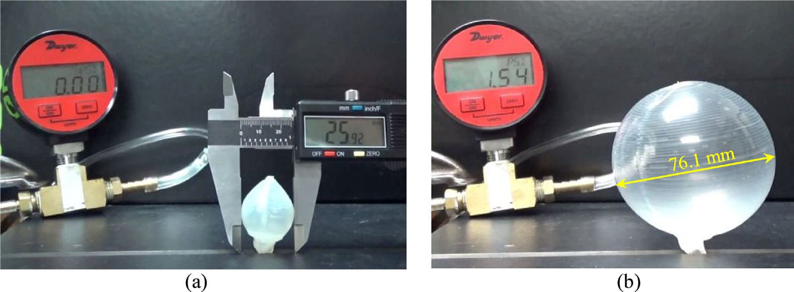
Figure 8: Burst pressure test of sphere-like balloon: (a): The 25.9 mm initial diameter measured with a caliper; and (b): The inflated close-to-rupture balloon with the diameter measured using the pixel-distance correlation of the image. (Adopted from [2])
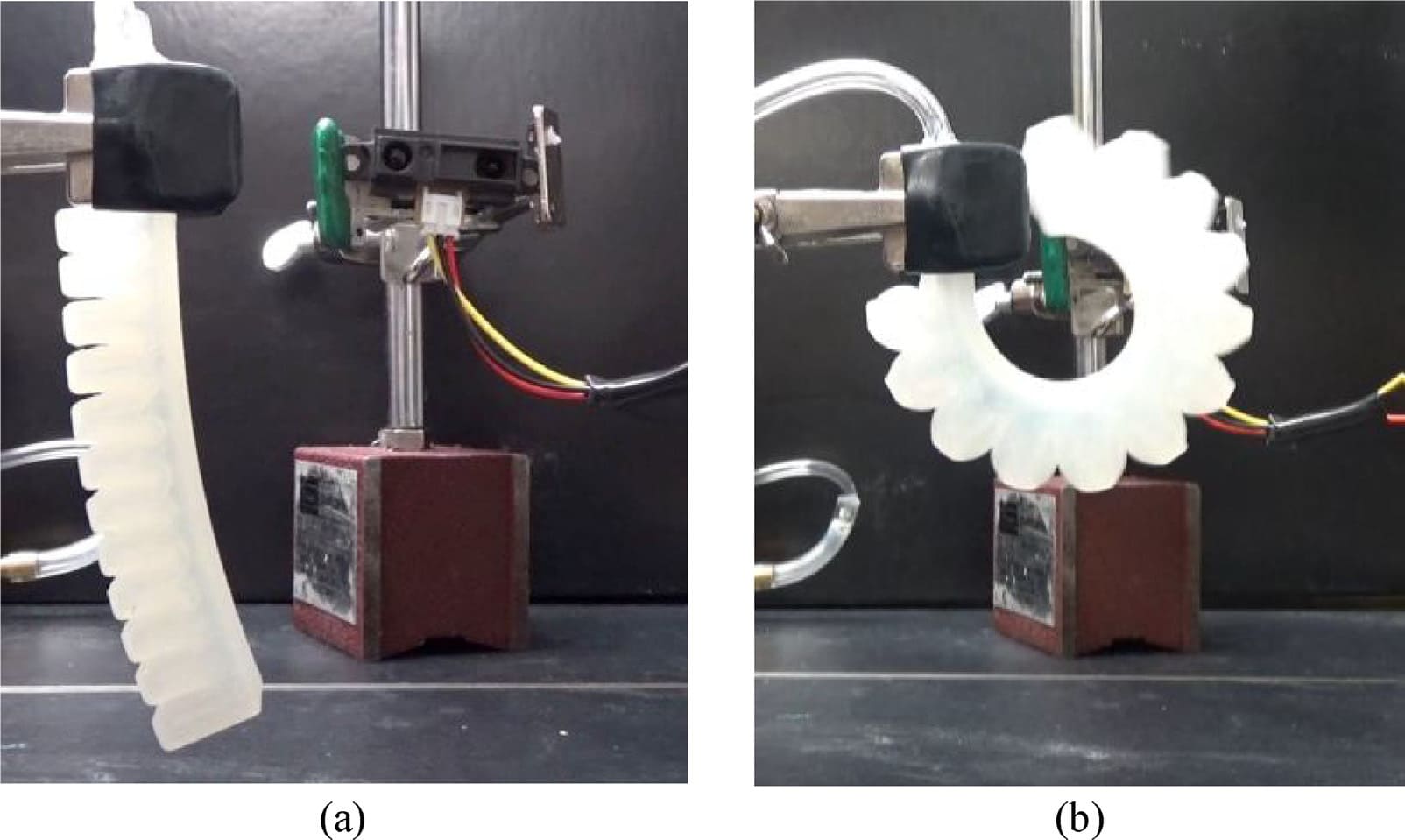
Figure 9: Finger pneumatic actuator in a (a): Non-articulated; and (b): Fully articulated configurations. (Adopted from [2]).
|
Medical Applications |
|
Function of Silicone |
|
Silicone implants |
Electronic Cochlear implants |
Encapsulate and insulate [6]. |
|
Cardiac Pacemaker |
Encapsulate and insulate [7]. |
|
|
Elastomer intraocular lenses |
Recover eyesight after retinal reattachment/cataract surgery [8]. |
|
|
Silicone tubing implant |
Conduit repair of median and ulnar nerves injuries in the forearm [9]. |
|
|
Breast implant |
Restoration of breast anatomy [10,11]. |
|
|
Hand/foot joint implant |
Interphalangeal joints replacement [12]. |
|
|
Extracorporeal equipment |
Silicone tubing |
Kidney dialysis, blood oxygenators, and heart bypass machines [13]. |
|
Silicone membranes |
Extraction of oxygen [14]. |
Table 1: Medical applications of silicones.
|
AM Technology |
Resolution um |
Printing Speeds (mm/s) |
|
Material Extrusion |
100 - 610 |
1 - 20 |
|
Freeform Reversible Embedding |
30- 700 |
2 - 20 |
|
Vat photopolymerization |
100- 400 |
Not reported |
|
Material Jetting |
Not reported |
5 |
|
Piezoelectric-Pneumatic Jetting |
500-600 |
104 |
Table 2: Comparison of the silicone printing features for available AM techniques.
References
5. PICSIMA patent P751510GB-PCT/PF
6. Lahey FH (1946) Comments made following the speech “Results from using Vitallium tubes in biliary surgery,” read by Pearse, HE before the American Surgical Association, Hot Springs, VA Ann Surg 124: 1027.
11. Cronin TD, Gerow FJ (1963) Augmentation mamma- plasty: A new “natural feel” prosthesis. Transactions of the Third International Congress of Plastic Surgery. Excerpta Medica. Int Congr Ser 41.
17. Jewell ML (2012) Silicone gel breast implants at 50: the state of the science 2012.
21. Mazas FB (1973) Guepar total knee prosthesis. Clin Orthop Rel Res 94: 211-221.
© by the Authors & Gavin Publishers. This is an Open Access Journal Article Published Under Attribution-Share Alike CC BY-SA: Creative Commons Attribution-Share Alike 4.0 International License. Read More About Open Access Policy.